Users Manual
Be sure to read the entire manual before using the shuttle.
Shuttle Details
Length: 7.0 M
Beam: 3.7 M
Height: 2.8 M
Mass: 3.97 M.T.
Identification Nubmers
Crew identification numbers are written in the the universal standard form.
They are also used to access assigned equipment.
| 1 | .png) |
2 | .png) |
3 | .png) |
| 4 | .png) |
5 | .png) |
6 | .png) |
| 7 | .png) |
8 | .png) |
9 | .png) |
Numbers are read in the following order: lower-left, lower-right, upper-left, and upper-right.
Example:  is read 3579
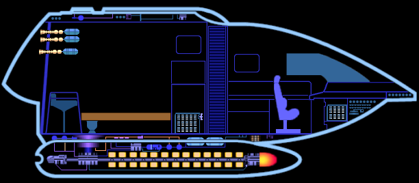
Status Display
Quickly determine the status of the shuttles systems by the status light next to the system name.
Status Indicators
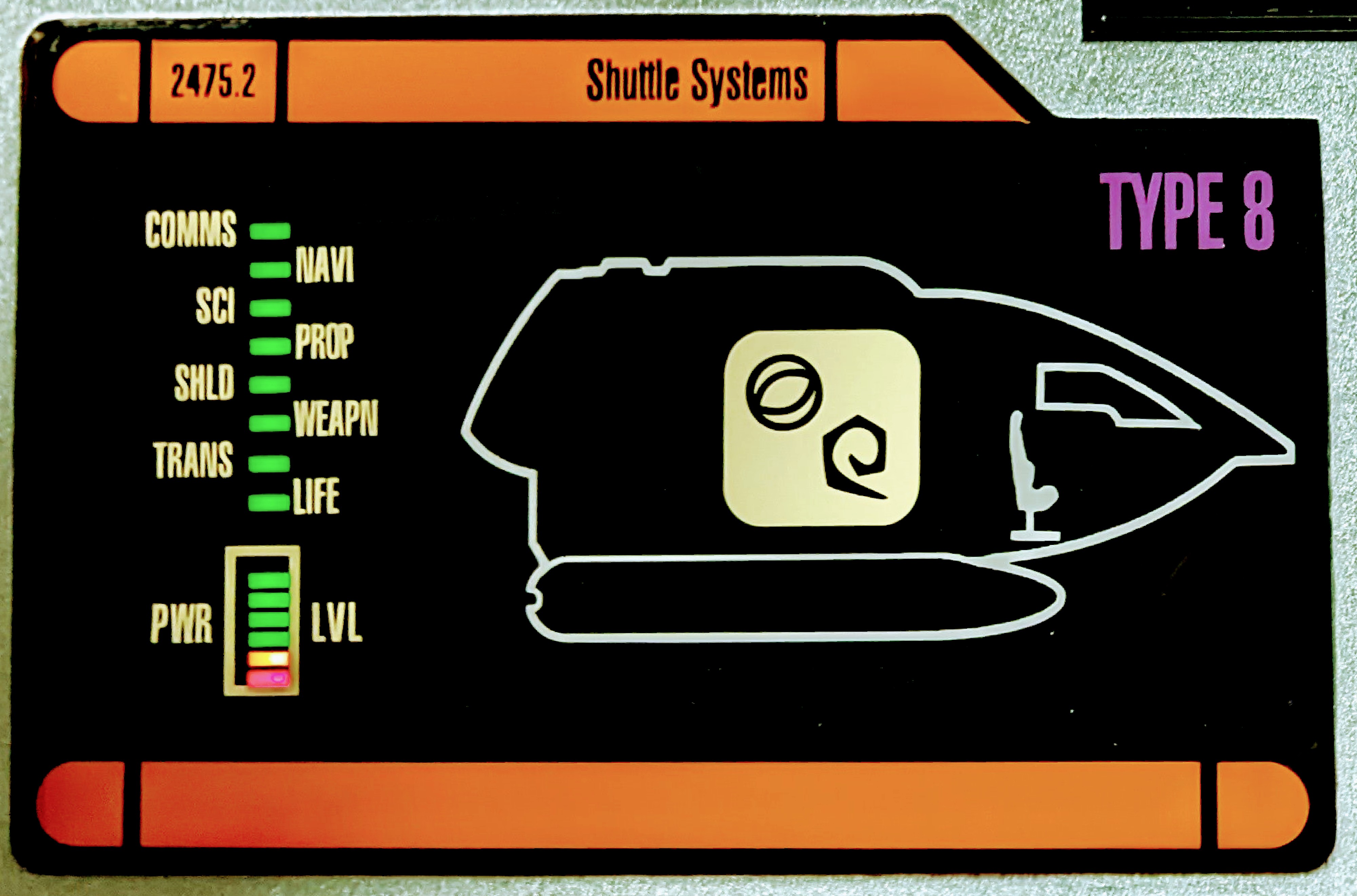
Computer System
Computer controls are dynamic and will automatically switch between directional and numerical mode when needed.
Users can also retrieve data from the computer via NFC by holding their tri-corder (smart phone) over the NFC logo.
While a standard set of commands are available, the computer system can be reprogrammed to perform other functions by re-configuring the Isolinear chips.
Power System
The power system is self-regulated and will do it's best to provide all systems with adequate power at any given time.
If main power fails for any reason you must attach the emergency power bank to the main power grid to restore power. While operating on emergency reserve power only a limited number of power slots can be active at a time. The power system will automatically prioritize power to the top 3 operational and essential systems.
If necessary you can manually route power to specific systems using the main power grid. Some system require more than one wire. Connecting only some of the wires for that system will reduce the power available to that system.
Power Grid Chart
Emergency Transporter
You can activate the Emergency Transporter at any time by pressing the dedicated command key *.
In case of an emergency this shuttle is equipped with a short range transporter that will attempt to beam all life inside the shuttle to safety. If no safe destination is available the status indicator will be yellow and flash quickly when attempting to use.
Science & Navigation
This shuttle is equipped with long range scanners used for finding items in the vicinity of the shuttle and for navigation.
It is also equipped with a material analyzer (shuttle diagram) useful in identifying items and materials.
Communication
This shuttle is capable of sending and receiving long and short range communications
At times the communication system may need to be re-calibrated to work in abnormal conditions.
Calibration Procedure
Calibration is a simple procedure that can be performed my any crew member.
- Using the computer, navigate to the communications system.
- Select calibration.
- Enter a 4 digit calibration code. (Any 4 digit code will do.)
- The system will indicate how many digits in your code are in the correct position (POS) and how many digits are the correct number (NUM).
- Using the feedback from the sysetm repeat steps 3 and 4 until you find the correct numbers and place them in the correct posision.
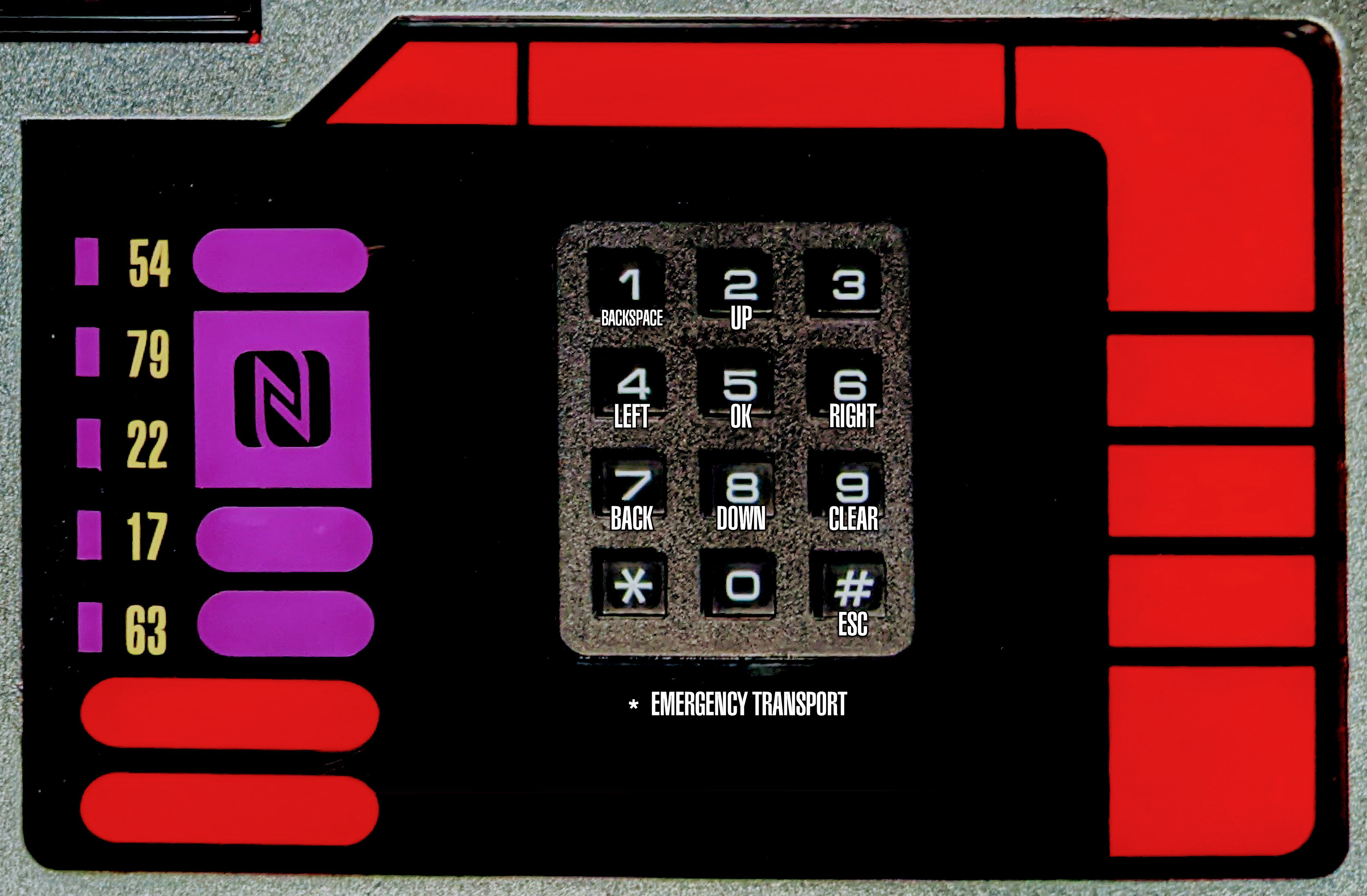
Tool Guide
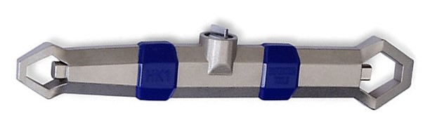
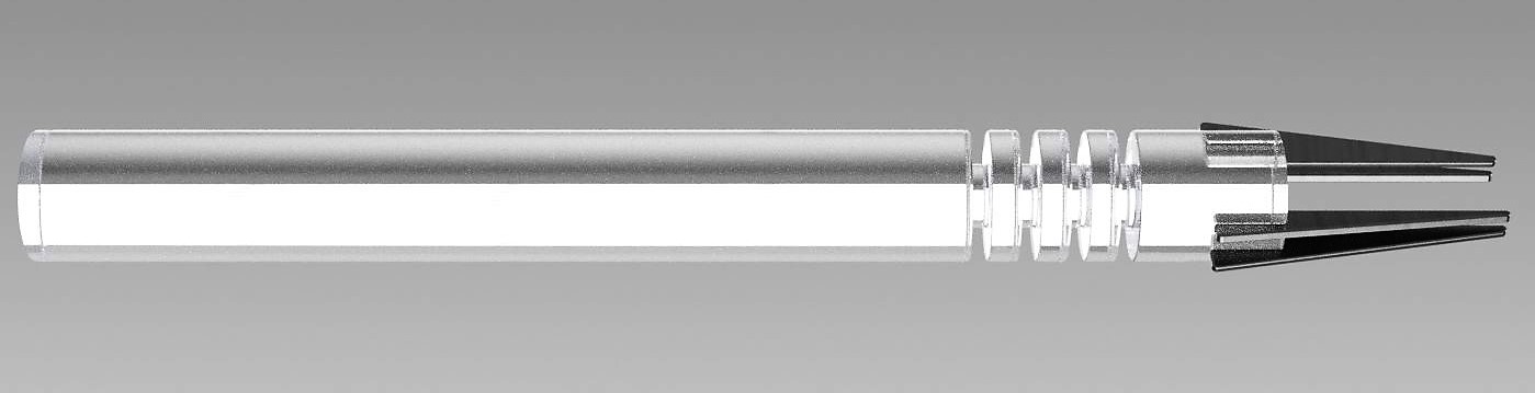
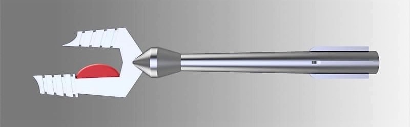
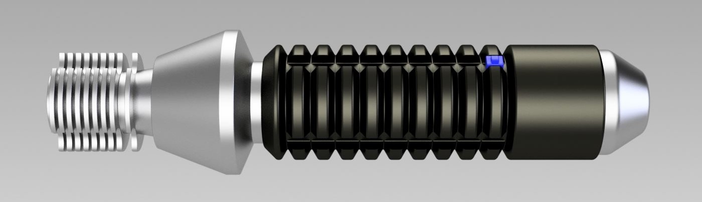
Repair Instructions
Use the tools on the shuttle diagram in the order indicated in the table below to repair the different systems of the shuttle.
The repair table appears to have been corrupted! You will need to rebuild the data before attempting any repairs.